STM32輸入捕獲模式設置并用DMA接收數據

參考:STM32的PWM輸入模式設置并用DMA接收數據
Input capture mode
The input stage samples the corresponding TIx input to generate a filtered signal TIxF.
本文引用地址:http://cqxgywz.com/article/201611/318505.htmThen, an edge detector with polarity selection generates a signal (TIxFPx)
which can beused as trigger input by the slave mode controller or as the capture command.
It isprescaled before the capture register (ICxPS).

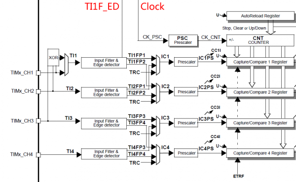
In Input capture mode, the Capture/Compare Registers (TIMx_CCRx) are used to latch thevalue of the counter
after a transition detected by the corresponding ICx signal.
When acapture occurs, the corresponding CCXIF flag (TIMx_SR register) is set and an interrupt
ora DMA request can be sent if they are enabled.
If a capture occurs while the CCxIF flag wasalready high, then the over-capture flag CCxOF (TIMx_SR register) is set.
CCxIF can becleared by software by writing it to ‘0’ or by reading the captured data stored in theTIMx_CCRx register.
CCxOF is cleared when you write it to ‘0’.
The following example shows how to capture the counter value in TIMx_CCR1 when TI1input rises.
To do this, use the following procedure:
? Select the active input:
TIMx_CCR1 must be linked to the TI1 input, so write the CC1Sbits to 01 in the TIMx_CCMR1 register.
As soon as CC1S becomes different from 00,the channel is configured in input and the TIMx_CCR1 register becomes read-only.
? Program the input filter duration you need with respect to the signal you connect to thetimer
(by programming ICxF bits in the TIMx_CCMRx register if the input is a TIx input).
Let’s imagine that, when toggling, the input signal is not stable during at must 5 internalclock cycles.
We must program a filter duration longer than these 5 clock cycles.
Wecan validate a transition on TI1 when 8 consecutive samples with the new level havebeen detected (sampled at fDTS frequency).
Then write IC1F bits to 0011 in theTIMx_CCMR1 register.
? Select the edge of the active transition on the TI1 channel by writing CC1P and CC1NPbits to 0
in the TIMx_CCER register (rising edge in this case).
? Program the input prescaler. In our example, we wish the capture to be performed ateach valid transition,
so the prescaler is disabled (write IC1PS bits to ‘00’ in theTIMx_CCMR1 register).
? Enable capture from the counter into the capture register by setting the CC1E bit in theTIMx_CCER register.
? If needed, enable the related interrupt request by setting the CC1IE bit in theTIMx_DIER register,
and/or the DMA request by setting the CC1DE bit in theTIMx_DIER register.
When an input capture occurs:
? The TIMx_CCR1 register gets the value of the counter on the active transition.
? CC1IF flag is set (interrupt flag). CC1OF is also set if at least two consecutive capturesoccurred whereas the flag was not cleared.
? An interrupt is generated depending on the CC1IE bit.
? A DMA request is generated depending on the CC1DE bit.
In order to handle the overcapture, it is recommended to read the data before theovercapture flag.
This is to avoid missing an overcapture which could happen after readingthe flag and before reading the data.
Note:
IC interrupt and/or DMA requests can be generated by software by setting thecorresponding CCxG bit in the TIMx_EGR register.
STM32輸入捕獲模式設置并用DMA接收數據
本文博客鏈接:http://blog.csdn.net/jdh99,作者:jdh
環境:
主機:WIN7
開發環境:MDK4.72
MCU:STM32F103
說明:
項目中需要進行紅外學習,于是采用輸入捕獲取得電平變化時間.并將數據放在DMA中.這樣可以避免頻繁中斷消耗CPU資源.
采用的是PB1腳,對應TIM3的通道4.
/********************************************************************** 接口函數:初始化紅外學習模塊**********************************************************************/void inf_infrared_study_init(void){//初始化io口inf_init_io();//初始化中斷//inf_init_irq();//初始化定時器inf_init_timer();//打開DMAinf_infrared_study_open_dma(1);//打開定時器inf_infrared_study_open_timer(1);}/********************************************************************** 初始化io口**********************************************************************/static void inf_init_io(void){//定義IO初始化結構體GPIO_InitTypeDef GPIO_InitStructure;//初始化時鐘RCC_APB2PeriphClockCmd(RCC_APB2Periph_GPIOB,ENABLE);//管腳初始化 GPIO_InitStructure.GPIO_Pin = GPIO_Pin_1;//設置為輸入 GPIO_InitStructure.GPIO_Mode = GPIO_Mode_IN_FLOATING; //初始化 GPIO_Init(GPIOB, &GPIO_InitStructure); }/********************************************************************** 初始化中斷**********************************************************************/static void inf_init_irq(void){//定義外部中斷結構體EXTI_InitTypeDef EXTI_InitStructure;//初始化中斷腳復用時鐘RCC_APB2PeriphClockCmd(RCC_APB2Periph_AFIO,ENABLE);//配置中斷源GPIO_EXTILineConfig(GPIO_PortSourceGPIOB,GPIO_PinSource1);// 配置下降沿觸發EXTI_ClearITPendingBit(EXTI_Line1);EXTI_InitStructure.EXTI_Line = EXTI_Line1;EXTI_InitStructure.EXTI_Trigger = EXTI_Trigger_Falling;EXTI_InitStructure.EXTI_Mode = EXTI_Mode_Interrupt;EXTI_InitStructure.EXTI_LineCmd = ENABLE;EXTI_Init(&EXTI_InitStructure);}/********************************************************************** 初始化定時器**********************************************************************/static void inf_init_timer(void){//定義定時器結構體TIM_TimeBaseInitTypeDef timInitStruct;//輸入捕獲結構體TIM_ICInitTypeDef tim_icinit;//定義DMA結構體DMA_InitTypeDef DMA_InitStructure;//啟動DMA時鐘RCC_AHBPeriphClockCmd(RCC_AHBPeriph_DMA1, ENABLE);//DMA1通道3配置DMA_DeInit(DMA1_Channel3);//外設地址DMA_InitStructure.DMA_PeripheralBaseAddr = (uint32_t)(&TIM3->CCR4);//內存地址DMA_InitStructure.DMA_MemoryBaseAddr = (uint32_t)Rx_Buf_Tim_Dma;//dma傳輸方向單向DMA_InitStructure.DMA_DIR = DMA_DIR_PeripheralSRC;//設置DMA在傳輸時緩沖區的長度DMA_InitStructure.DMA_BufferSize = RX_LEN_TIM_DMA;//設置DMA的外設遞增模式,一個外設DMA_InitStructure.DMA_PeripheralInc = DMA_PeripheralInc_Disable;//設置DMA的內存遞增模式DMA_InitStructure.DMA_MemoryInc = DMA_MemoryInc_Enable;//外設數據字長DMA_InitStructure.DMA_PeripheralDataSize = DMA_PeripheralDataSize_HalfWord;//內存數據字長DMA_InitStructure.DMA_MemoryDataSize = DMA_MemoryDataSize_HalfWord;//設置DMA的傳輸模式//DMA_InitStructure.DMA_Mode = DMA_Mode_Normal;DMA_InitStructure.DMA_Mode = DMA_Mode_Circular;//設置DMA的優先級別DMA_InitStructure.DMA_Priority = DMA_Priority_High;//設置DMA的2個memory中的變量互相訪問DMA_InitStructure.DMA_M2M = DMA_M2M_Disable;DMA_Init(DMA1_Channel3,&DMA_InitStructure); //開啟時鐘RCC_APB1PeriphClockCmd(RCC_APB1Periph_TIM3,ENABLE);//重新將Timer設置為缺省值TIM_DeInit(TIM3);//采用內部時鐘給TIM3提供時鐘源TIM_InternalClockConfig(TIM3);//預分頻timInitStruct.TIM_ClockDivision = TIM_CKD_DIV1; //計數頻率為500ns跳轉1次 timInitStruct.TIM_Prescaler = SystemCoreClock / 2 - 1; //向上計數 timInitStruct.TIM_CounterMode = TIM_CounterMode_Up; timInitStruct.TIM_RepetitionCounter = 0;//這個值實際上就是TIMX->ARR,延時開始時重新設定即可 timInitStruct.TIM_Period = 0xffff; //初始化定時器3TIM_TimeBaseInit(TIM3, &timInitStruct);//輸入捕獲配置//選擇通道tim_icinit.TIM_Channel = TIM_Channel_4;//硬件濾波tim_icinit.TIM_ICFilter = 0x0;//觸發捕獲的電平tim_icinit.TIM_ICPolarity = TIM_ICPolarity_Falling;//每次檢測到觸發電平都捕獲tim_icinit.TIM_ICPrescaler= TIM_ICPSC_DIV1;//通道方向選擇tim_icinit.TIM_ICSelection = TIM_ICSelection_DirectTI;//初始化TIM_ICInit(TIM3,&tim_icinit);//禁止ARR預裝載緩沖器 TIM_ARRPreloadConfig(TIM3, DISABLE); //輸入跳變選擇TIM_SelectInputTrigger(TIM3, TIM_TS_TI2FP2);//從機模式:復位模式TIM_SelectSlaveMode(TIM3, TIM_SlaveMode_Reset);//主從模式選擇TIM_SelectMasterSlaveMode(TIM3, TIM_MasterSlaveMode_Enable);//配置定時器的DMATIM_DMAConfig(TIM3,TIM_DMABase_CCR4,TIM_DMABurstLength_2Bytes);//產生DMA請求信號TIM_DMACmd(TIM3, TIM_DMA_CC4, ENABLE);//打開定時器TIM_Cmd(TIM3, ENABLE);}/********************************************************************** 接口函數:打開定時器*參數:state:狀態:0:關閉,1:打開**********************************************************************/void inf_infrared_study_open_timer(uint8_t state){if (state){TIM_Cmd(TIM3, ENABLE);}else{TIM_Cmd(TIM3, DISABLE);}}/********************************************************************** 接口函數:打開中斷*參數:state:狀態:0:關閉,1:打開**********************************************************************/void inf_infrared_study_open_irq(uint8_t state){//定義中斷結構體NVIC_InitTypeDef NVIC_InitStructure ;if (state){//打開中斷NVIC_InitStructure.NVIC_IRQChannel = EXTI1_IRQn; //通道設置為外部中斷線NVIC_InitStructure.NVIC_IRQChannelPreemptionPriority = 1; //中斷搶占先等級NVIC_InitStructure.NVIC_IRQChannelSubPriority = 0; //中斷響應優先級NVIC_InitStructure.NVIC_IRQChannelCmd = ENABLE; //打開中斷NVIC_Init(&NVIC_InitStructure); //初始化}else{//關閉中斷NVIC_InitStructure.NVIC_IRQChannel = EXTI1_IRQn; //通道設置為外部中斷線NVIC_InitStructure.NVIC_IRQChannelPreemptionPriority = 1; //中斷搶占先等級NVIC_InitStructure.NVIC_IRQChannelSubPriority = 0; //中斷響應優先級NVIC_InitStructure.NVIC_IRQChannelCmd = DISABLE; //打開中斷NVIC_Init(&NVIC_InitStructure); //初始化}}/********************************************************************** 接口函數:打開DMA*參數:state:狀態:0:關閉,1:打開**********************************************************************/void inf_infrared_study_open_dma(uint8_t state){if (state){//設置傳輸數據長度//DMA_SetCurrDataCounter(DMA1_Channel3,RX_LEN_TIM_DMA);//打開DMADMA_Cmd(DMA1_Channel3,ENABLE);}else{DMA_Cmd(DMA1_Channel3,DISABLE);}}/********************************************************************** 接口函數:得到DMA接收幀長*返回:幀長**********************************************************************/uint16_t inf_infrared_study_dma_rx_len(void){//獲得接收幀幀長return (RX_LEN_TIM_DMA - DMA_GetCurrDataCounter(DMA1_Channel3));}注意:
除TIM6和TIM7之外的定時器都只能采用上升沿或者下降沿捕捉而不能采用雙邊沿捕捉.
#define TIM_ICPolarity_Rising ((uint16_t)0x0)#define TIM_ICPolarity_Falling ((uint16_t)0x2)#define TIM_ICPolarity_BothEdge ((uint16_t)0xA)#define IS_TIM_IC_POLARITY(POLARITY) (((POLARITY) == TIM_ICPolarity_Rising) ((POLARITY) == TIM_ICPolarity_Falling))#define IS_TIM_IC_POLARITY_LITE(POLARITY) (((POLARITY) == TIM_ICPolarity_Rising) ((POLARITY) == TIM_ICPolarity_Falling) ((POLARITY) == TIM_ICPolarity_BothEdge))

評論